arrow_back_ios
Main Menu
arrow_back_ios
Main Menu
- Accessories
- Actuators
- Combustion Engines
- Durability
- eDrive
- Mobile Systems
- Production Testing Sensors
- Transmission Gearboxes
- Turbo Charger
- DAQ systems
- High precision and calibration systems
- Industrial electronics
- Power Analyser
- S&V Handheld devices
- S&V Signal conditioner
- testing
- HATS (Head and torso simulator)
- Artificial Ear
- Electroacoustic hardware
- Bone conduction
- Electroacoustic software
- Accessories for electroacoustic application
- Pinnae
- Accessories for electroacoustic application
- DAQ
- Drivers API
- nCode - Durability and Fatigue Analysis
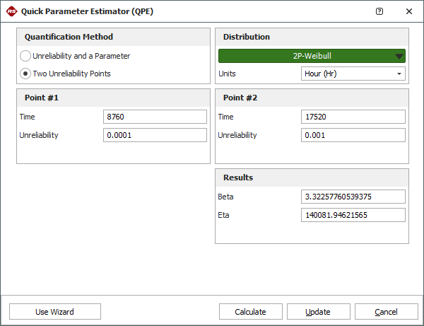
- ReliaSoft - Reliability Analysis and Management
- Test Data Management
- Utility
- Vibration Control
- Acoustic
- Current / voltage
- Displacement
- Force sensors
- Load cells
- Multi Component Sensors
- Pressure
- Strain Gauges
- Strain Sensors
- Temperature Sensors
- Tilt Sensors
- Torque
- Vibration
- Temperature
- LDS Shaker Systems
- Power Amplifiers
- Vibration Controllers
- Measurement Exciters
- Modal Exciters
- Accessories for modal exciters
- Artificial Ear
- Artificial Mouth
- Bone Conduction
- Data Acquisition
- HATS Head Torso Simulator
- Microphone
- Signal Conditioning
- Test Solutions
- Accessories Electroacoustic Application
arrow_back_ios
Main Menu
- Bridge calibration units
- Microphone calibration system
- Sound level meter calibration system
- Strain Gauge precision instrument
- Vibration transducer calibration system
- Accessories for high precision and calibration systems
- Multi channel amplifier
- Single channel amplifier and amplifier with display
- Weighing indicators
- Weighing electronics
- Accessories for industrial electronics
- Piezoelectric
- Weighing electronics
- Press fit controller
- Weighing indicators
- CCLD (IEPE) signal conditioner
- Charge signal conditioner
- Microphone signal conditioner
- NEXUS
- Accessories for signal conditioner
- BK Connect / PULSE
- catman Enterprise
- catmanEasy AP
- Software Downloads for Perception / Genesis HighSpeed
- Tescia
- Test for I-deas
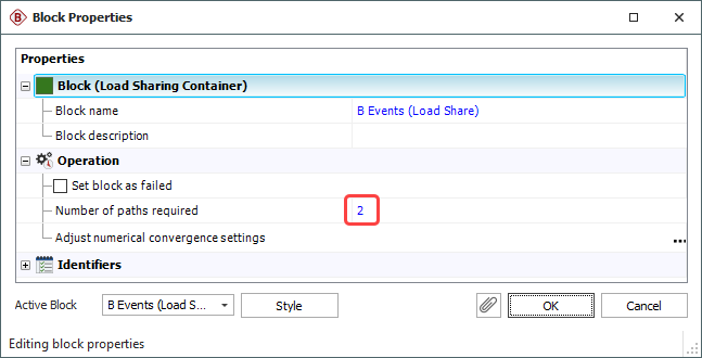
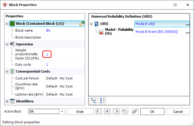
- ReliaSoft BlockSim
- ReliaSoft Cloud
- ReliaSoft Lambda Predict
- ReliaSoft Product Suites
- ReliaSoft RCM++
- ReliaSoft XFMEA
- ReliaSoft XFRACAS
- ReliaSoft Weibull++
- Classical Shock
- Random
- Random-On-Random
- Shock Response Spectrum Synthesis
- Sine-On-Random
- Time Waveform Replication
- Vibration Control Software
- Microphone sets
- Microphone Cartridges
- Acoustic calibrators
- Hydrophones
- Special microphones
- Microphone Pre-amplifiers
- Sound Sources
- Accessories for acoustic transducers
- Test automatic
- Fiber Optic Technology
- Inductive technology
- Strain gauge technology
- Accessories for displacement sensors
- Bending / beam
- Canister
- Compression
- Single Point
- Tension
- Weighing modules
- Accessories for load cells
- Experimental testing
- Fiber Optic Technology
- Transducer Manufacturing (OEM)
- Accessories for strain gauges
- CCLD (IEPE) accelerometer
- Charge accelerometer
- Fiber Optic Accelerometer
- Force transducers
- Reference accelerometer
- Impulse hammers / impedance heads
- Tachometer probes
- Vibration calibrators
- Cables
- Accessories for vibration transducers
- Accessories
- High-Force LDS Shakers
- Medium-Force LDS Shakers
- Low-Force LDS Shakers
- Permanent Magnet Shakers
- Shaker Equipment / Slip Tables
- Fatigue and Durability Analysis Training
- Reliability Training Courses
- Sound and Vibration Courses
- HBM Courses
- Delete content
- Request Calibration
- Calibration Services for Transducers
- Calibration Services for Handheld Instruments
- Calibration Services for Instruments & DAQ
- Resources
- Electroacoustics
- Environmental Noise
- Noise Source Identification
- Product Noise
- Ramp Noise Testing
- Static Engine Noise Certification
- Sound Power and Sound Pressure
- Flight Certification
- Acoustic material testing
- Vehicle Pass-by Noise
- Production Testing and Quality Assurance
- Machine Analysis and Diagnostics
- Structural Health Monitoring
- OEM Sensors for the Agriculture Industry
- OEM Sensors for Robotics and Torque Applications
- OEM Sensors Medical
arrow_back_ios
Main Menu
- Housing
- Communication processor
- Amplifier modules
- Connection boards
- Special function modules
- Accessories for MGCplus
- Binaural Audio
- Outdoor microphones
- Probe Microphones
- Sound intensity probes
- Surface microphone
- Array microphones
- Other special microphones
- Production line test
- Microphone Cables
- Tripods
- Microphone booms
- Microphone adapters
- Electrostatic actuators
- Microphone windscreen
- Nose cones
- Microphone holders
- Tripods
- Other accessories for acoustic transducers
- Microphones outdoor protection
- Adhesives
- Protective coatings
- Cleaning material
- SG Kits
- Solder terminals
- Other strain gauge accessories
- Cables
- ZeroPoint Balancing
- TCS Balancing
- TC0 Balancing
- Magnets
- Mounting clips/bases
- Studs, screws and washers
- Adhesives/Tools
- Adapters
- Mechanical filters
- Other accessories
- Calibration of Microphone and Preamplifier
- Calibration of Accelerometers
- Pressure Calibration
- Displacement
- Calibration of Sound Level Meters
- Calibration of Sound Calibrator and Pistonphone
- Vibration Meter
- Vibration Calibrator
- Noise Dosimeter Calibration
- Telephone Headset And Handset Testing
- Testing Of Hands-Free Devices
- Headphone Testing
- Hearing Aid Testing
- Speaker Testing
- Smart Speaker Testing
- Acoustic Holography
- Underwater Acoustic Ranging
- Wind Tunnel Acoustic Testing – Aerospace
- Wind Tunnel Testing For Cars
- Beamforming
- Questions
- Flyover Noise Source Identification
- Real-Time Noise Source Identification With Acoustic Camera
- Sound Intensity Mapping
- Spherical Beamforming
- Order Analysis
- Machine Diagnostics
- Health and Usage Monitoring Systems (HUMS)
- Gas Turbine Testing
- Questions for Machine Analysis
- Tunnel monitoring with Fiber Bragg sensors
- Monitoring Solutions for Civil Infrastructures
- Monitoring Solutions for Wind Turbines
- Monitoring Solutions for the Oil and Gas Industry
- Monitoring Solutions for Railways
- Monitoring Solutions for Civil Engineering
- Available Monitoring Services
- Foundation Monitoring Using Strain Gauges
- Switchgear Tests
- Transformer Equivalent Circuit Diagram | HBM
- Current Zero Testing
- Testing High Power Circuit Breakers Safely