


Aug 29 2019
Strain Gauge Fundamentals
Read More
Careers | Training | Resource!!!
As part of a span enlargement project of the Akaflieg Darmstadt D-43 glider, new outer wings based on a fibre-plastic composite structure must be manufactured. To receive the certification of the new outer wings by the German Federal Aviation Authority (LBA), load tests were carried out to verify the previously performed strain simulations of the finite element model.
Challenge
In order to obtain the approval by the German Federal Aviation Authority (LBA), Akaflieg Darmstadt has to test the load of its newly manufactured glider outer wing.
Solution
Strain simulations have already been performed on a finite element model, which must now be verified. Therefore, HBK strain gauges, installed at different positions of the outer wing, are used to determine the strains on the component surface and to validate the simulated strain curves.
Result
The measurement results show that the finite element model simulation delivers very realistic results with only a few deviations.
Due to the span increase from 18 m to 20 m, the length of the new outer wings increased to 1.5 m. For the load tests of the fibre-plastic composite structure, the temperature is at least 54°C. The load will correspond to 172.5% of the maximum loads occurring during operation.
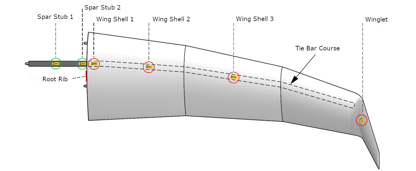
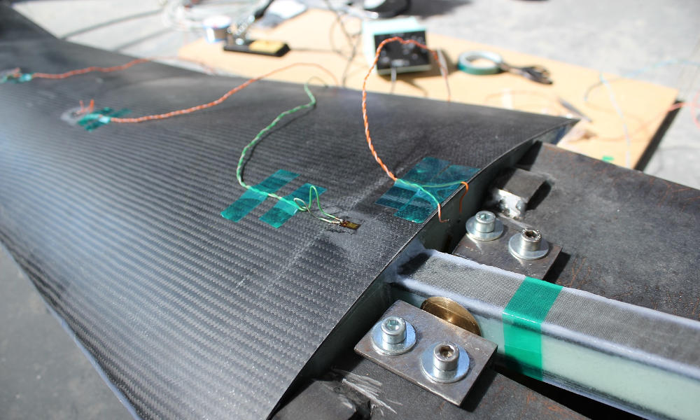
HBK's M series strain gauges for high alternating loads (1-LM16-6/350GE) are used to determine the strain on the component surface. Installed at different positions on the outer wing, the strain gauges are aligned in the fibre direction of the unidirectional (UD) bands of the fibre-plastic composite beam:
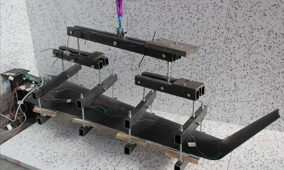
The load on the outer wing is applied by a crane and distributed via the load harness to four points on the underside of the wing. The lever arms of the load harness are adjusted in such a way that the bending moment, shear force and torsion moment curves occurring in flight are realistically represented.
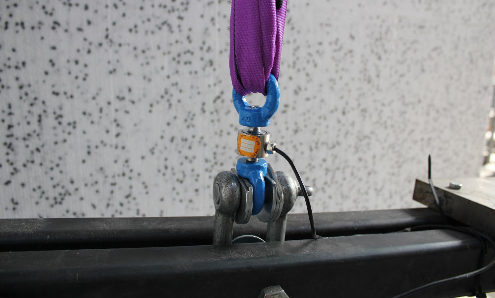
The crane force is introduced at the upper beam and measured with a HBK miniature load cell U9C (1-U9C/20KN). To set the temperature of 54 °C, the outer wing is located in a heat cabin made of Styrofoam with fan heater.
The results of the load test (strains and deformations) are used to validate the existing finite element model simulation of the outer wing. During the simulation, two strain curves were calculated on the upper side of the wing for Limit Load (100% maximum load - blue graph) and Ultimate Load (172.5% maximum load - orange graph).
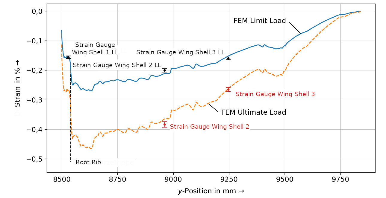
The strain curves of the finite element model simulation provide very realistic results. The determined deformations deviate by a maximum of 4 %, strains by a maximum of 5 %. Reasons for the deviations are uncertainties in:
Under the motto "Research, Build, Fly", new types of gliders have been created at the Akaflieg Darmstadt since 1920. The Akademische Fliegergruppe Darmstadt (short Akaflieg) is a university group of the TU Darmstadt. They pursue the goal of researching motorless flying using thermals, building gliders and trying out innovative concepts.

This will bring together HBM, Brüel & Kjær, nCode, ReliaSoft, and Discom brands, helping you innovate faster for a cleaner, healthier, and more productive world.
This will bring together HBM, Brüel & Kjær, nCode, ReliaSoft, and Discom brands, helping you innovate faster for a cleaner, healthier, and more productive world.
This will bring together HBM, Brüel & Kjær, nCode, ReliaSoft, and Discom brands, helping you innovate faster for a cleaner, healthier, and more productive world.
This will bring together HBM, Brüel & Kjær, nCode, ReliaSoft, and Discom brands, helping you innovate faster for a cleaner, healthier, and more productive world.
This will bring together HBM, Brüel & Kjær, nCode, ReliaSoft, and Discom brands, helping you innovate faster for a cleaner, healthier, and more productive world.