Chat with us, powered by LiveChat
arrow_back_ios

Main Menu

See All Acoustic End-of-Line Test Systems See All DAQ and instruments See All Electroacoustic application See All Software See All Transducers See All Vibration Testing Equipment See All Electroacousticsb - OLD unpublished See All Academy See All Resource Center See All Services See All Support See All Applications See All Industries See All Our Business
arrow_back_ios

Main Menu

See All Actuators See All Combustion Engines See All Durability See All eDrive See All Transmission Gearboxes See All Turbo Charger See All DAQ systems See All High precision and calibration systems See All Industrial electronics See All Power Analyser See All S&V Handheld devices See All S&V Signal conditioner See All Accessories for electroacoustic application See All DAQ See All Drivers API See All nCode - Durability and Fatigue Analysis See All ReliaSoft - Reliability Analysis and Management See All Test Data Management See All Utility See All Vibration Control See All Acoustic See All Current / voltage See All Displacement See All Load cells See All Pressure See All Strain Gauges See All Torque See All Vibration See All Temperature See All LDS Shaker Systems See All Power Amplifiers See All Vibration Controllers See All Accessories for modal exciters See All Test Solutions See All Training Courses See All Primers and Handbooks See All Calibration See All Installation, Maintenance & Repair See All Support Brüel & Kjær See All Acoustics See All Asset & Process Monitoring See All Electric Power See All NVH See All OEM Custom Sensors See All Structural Integrity See All Vibration See All Automotive & Ground Transportation See All Business Ethics
arrow_back_ios

Main Menu

See All CANHEAD See All GenHS See All LAN-XI See All MGCplus See All Optical Interrogators See All QuantumX See All SomatXR See All Fusion-LN See All Accessories for industrial electronics See All Handheld Software See All Accessories for S&V handheld devices See All BK Connect / PULSE See All API See All Microphone sets See All Microphone Cartridges See All Acoustic calibrators See All Special microphones See All Microphone Pre-amplifiers See All Sound Sources See All Accessories for acoustic transducers See All Experimental testing See All Transducer Manufacturing (OEM) See All Accessories for strain gauges See All Non-rotating (calibration) See All Rotating See All CCLD (IEPE) accelerometer See All Charge accelerometer See All Impulse hammers / impedance heads See All Cables See All Accessories See All Calibration Services for Transducers See All Calibration Services for Handheld Instruments See All Calibration Services for Instruments & DAQ See All Resources See All Electroacoustics See All Environmental Noise See All Noise Source Identification See All Product Noise See All Sound Power and Sound Pressure See All Vehicle Pass-by Noise See All Production Testing and Quality Assurance See All Machine Analysis and Diagnostics See All Structural Health Monitoring See All High Voltage See All OEM Sensors for the Agriculture Industry See All OEM Sensors for Robotics and Torque Applications See All Structural Dynamics See All Material Properties Testing
null

Torque Sensors Basic Knowledge

How Does a Torque Transducer Actually Work?

Although torque sensors are available in various designs, they all have a few things in common. To understand how torque transducers work, let’s take a look at the design of the sensors.

A Brief Trip Through Strain Gauge Technology

Like many other kinds of sensors, torque transducers use strain gauge technology for measurement. The sensor consists of a measuring body, generally of metal, on which strain gauges (SG) are mounted. These consist of a thin foil and an electrical conductor that is firmly connected to the foil. As the foil – and therefore the conductor – changes shape, the electrical resistance also changes. This reveals how much load is currently acting on the SG.

If an external load acts on the sensor, the strain gauge deforms as does the spring element – and measurement can commence. This applies not only to torque transducers, but also to load cells, force sensors, and other types of sensor. However, torque sensors have a few special features.

null

Two Typical Torque Sensor Designs

null

Unlike load cells or force transducers, the measuring body of a torque transducer is not subject to tension or compression when in use, but to torsion. The sensor is not exposed to a force acting from one or two opposing directions, but rather a lever force, or torque. Therefore, torque sensors are also fitted with special strain gauges that can record this type of load, that is, torsion, very well. Two typical torque transducer designs are the measurement shaft and the measurement flange.

Torque Measurement Shaft

The measurement shaft consists of a shaft, which may also be hollow. The SGs are mounted here – sometimes on a tapered section in the middle, for example, depending on the version. The shaft is enclosed by a housing. The shaft, or rotor, moves while the housing, or stator, is fixed. Both parts are interconnected by low-friction, zero-play bearings. The transducer can be incorporated in a structure or test bench by means of hub-type clamps on both ends of the shaft. These are available in various shapes and sizes.

null

Torque Measurement Flange

null

Measurement flanges basically have a similar structure to measurement shafts, but look completely different. They too consist of a mostly hollow shaft, although this is extremely short. Flanges are situated at both ends of the shaft. These enable the transducer to be integrated into a structure or test bench by means of a threaded connection. Measurement flanges also consist of a rotor and stator. However, unlike in measurement shafts, the rotor is not entirely enclosed in the housing. Therefore, no bearing assembly is needed because the rotor is securely installed in the measurement section.

Contactless Measured Data Transmission

This is where we see the biggest difference between rotating torque transducers and other sensors such as force transducers or load cells In rotating transducers, cables supplying power and transferring measurement data cannot be used because the cables would become entangled as the rotor turns. To avoid this, energy is transferred from the stator to the turning rotor using a contactless connection, which in turn supplies the mounted SG measuring bridge. In return, the turning rotor transfers the measured data to the stator via telemetry.

Electronics are housed in the measuring body. Here, the signal from the SG measuring bridge is amplified, filtered and digitized before being wirelessly transferred to the stator. The data can then be output either via a frequency or voltage signal or digitally via a fieldbus, for example, with EtherCAT or Profinet, depending on the application.

Rotating or Non-Rotating Torque Measurement

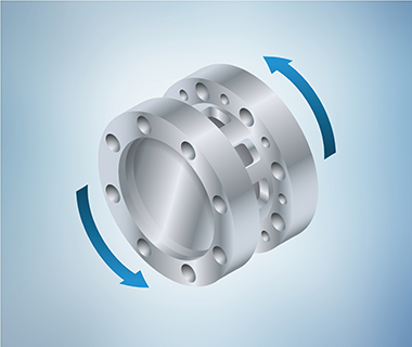
The transducer doesn’t always rotate when measuring torque. Typical examples of non-rotating setups are standard test machines and measurements on mixers. In the latter, the transducer is supported by the housing of the electric motor, and the drive shaft runs through a central hole in the sensor.

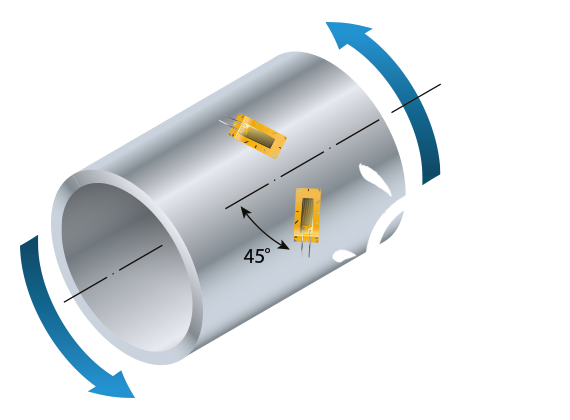
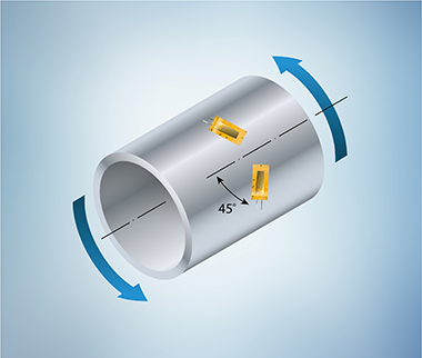
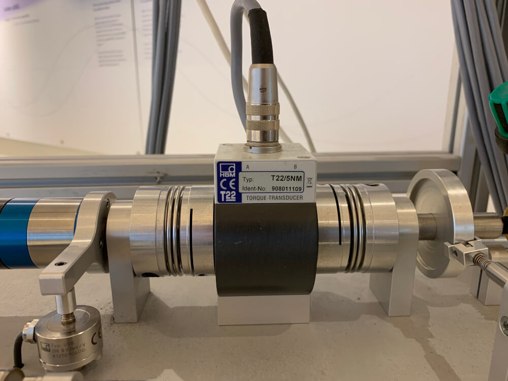
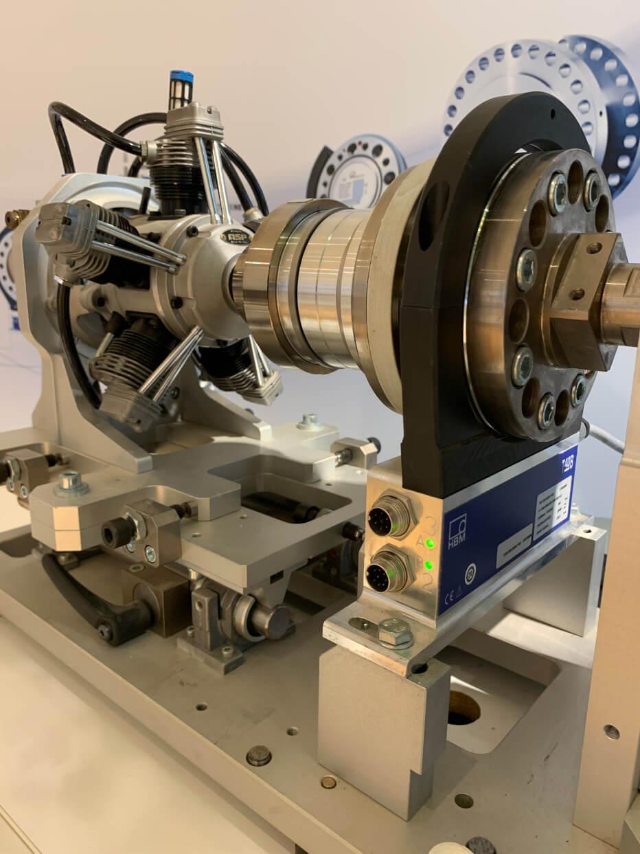
In most applications, the sensor is part of the rotating drivetrain between the test specimen and the dynamometer. The specimen could be an internal combustion engine, a gearbox, or an electric motor, for instance.

null

Static and Dynamic Torque Measurement

Torque can be measured statically or dynamically. An example of a dynamic measurement could be the pulsating torque generated when rotating elements are continually accelerated and then slowed down (or ‘braked’), or through the power stroke of an internal combustion engine. What’s more, dynamic torque can also occur completely without rotation. However, in most applications – such as engine test benches (internal combustion engine or electric motor) – dynamic torque occurs in connection with rotation.

More Than Just Torque

Torque sensors can do more. In addition to torque, other measured variables can be recorded with just one sensor. This is optional, but many torque transducers already come with this ability. The most obvious parameter is rotational speed, which can be measured by transmitting light through a slotted disk on the rotor. As the sensor turns, the beam of light is interrupted at certain intervals. When the time window is constant, the rotational speed is calculated simply by counting the pulses.

One important characteristic of interest to many users is power, which can be calculated by multiplying the torque by the rotational speed.

In addition, many torque transducers have a built-in temperature sensor, which can tell us how much the sensor or drivetrain is heating up, for example.

null

Typical Applications for Torque Transducers

Torque transducers are ideal for all kinds of engine, motor and drive tests in the field of research and development. Precise torque measurement is indispensable when you want to improve the efficiency of new drives, as it enables friction losses to be determined and minimized. In electric and hybrid motors, what matters is range and improving efficiency; in hybrid and internal combustion engines, the key is always environmental friendliness through the lowest possible CO2 emissions.

Moreover, torque sensors are used in end-of-line tests on transmissions and engines or in function tests on rotary switches. However, some applications look entirely different – such as when liquids are mixed and the process requires monitoring by a torque transducer. Or when torque sensors are installed in the powertrain of a ship. These transducers are also used as reference transducers in standard test machines.

HBK offers both torque measurement shafts and measurement flanges for a large variety of applications.


Torque Sensors

No more result to load

Further Reading